
Landslide monitoring - The case of an apennine landslide
Measuring sensors for landslide monitoring
Tecnopenta designs and builds landslide monitoring systems.
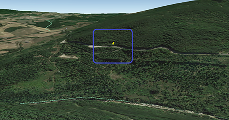
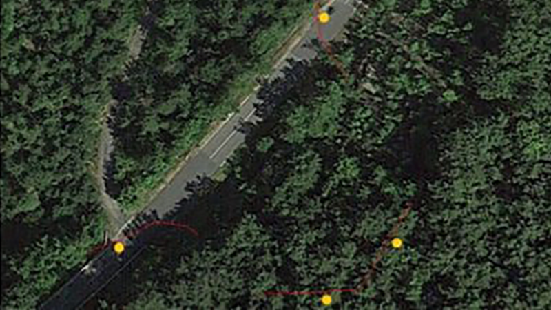
Here is a recent example, still in operation on a stretch of Tuscan provincial road affected by a landslide. We are in a hilly area at approximately 370 m above sea level, the portion of the road involved is approximately 60 m long and delimited by two twin fractures converging towards the mountain. The landslide also affects the wooded area next to the road characterized by the presence of various fractures and slides. In this landslide monitoring system it was therefore decided to install two measurement points on the road and two points in the wooded area upstream of the two carriageways.
Here is a recent example, still in operation on a stretch of Tuscan provincial road affected by a landslide. We are in a hilly area at approximately 370 m above sea level, the portion of the road involved is approximately 60 m long and delimited by two twin fractures converging towards the mountain. The landslide also affects the wooded area next to the road characterized by the presence of various fractures and slides. In this landslide monitoring system it was therefore decided to install two measurement points on the road and two points in the wooded area upstream of the two carriageways.
Measuring sensors for landslide monitoring
The monitoring of the movement in progress is made up of two pairs of strain gauge sensors: the first two positioned across the two fractures that cross the road and the second instead located on the fractures in the woods.
The instruments mounted on the fractures in the road are G1-EST CPL model wire strain gauges, mounted on specially constructed concrete plinths. The sensitive part of the instrument is a spring-tensioned rotary potentiometer with a 100 cm stroke which measures the displacement through a steel cable hooked to the opposite sides of the fracture. The main body of the instrument is housed in a Palazzoli IP68 box (10x10x10), made of plastic material and anchored to the plinth located on the side of the fracture considered stable.
The construction company was commissioned a set of 3 plinths for each measuring station: one on the side considered not to be moving and two on the landslide side. A pair of sides of the two plinths lies on an ideal line perpendicular to the direction of the fracturing so that the monitoring investigates the main resultant of the movement taking place and that the installation is precise.
Positioning of plinth
The image on the right shows the position of the plinths in relation to the fracture.
The third plinth, placed at a greater distance from the one considered stationary, will be used for mounting an on/off type alarm system.
The plinths are made of concrete, with a square base of 40 cm side and are anchored with steel bars with improved adhesion up to 1 m deep.
The tops of the plinths fall on the same plane so they are of different heights given that the landslide caused the dislocation of the side of the fracture towards the valley.
The plinths built for attaching the wire strain gauge are approximately 250 cm apart.

Example of plinth positioning
Strain gauge sensor for landslide monitoring

Strain gauge sensor for landslide monitoring
he instruments mounted on the fractures in the forest are G1-EST S model wire surface strain gauges. In this case the tensioning system consists of a weight of 8 kg and the sensitive part is a multi-turn potentiometer with a stroke of 130 cm.
The stainless steel wire which has the task of transferring the movement to the potentiometer runs on an appropriately sized aluminum pulley.
The main body of the instrument is assembled on a pole driven into the ground, on the upstream side of the fracture, while the steel cable, that acts as a measurement base, is anchored on the other side of the crack.
The stainless steel cable is held in position by height-adjustable brass wire guides driven into the ground. The boxes used for the construction of these sensors are Rittal ones (20 x 11 x 30 cm) in painted metal.
Data acquisition
In both measurement stations the data acquisition is entrusted to a FlexLog model data logger. The FlexLog is a multi-channel logger (the number of channels is chosen based on the sensors), with very low consumption and which can be equipped with a GPRS module for sending data to a remote server. Furthermore, the data is also stored in situ on an SD memory card, which can be removed and read with any PC without any special software.
The logger assigned to the forest station is housed in a Bocchiotti box made of fiberglass and equipped with a key lock. Logger is supplied by a 4.2 V lithium ion battery backed up by a 7 Ah lead acid battery. In addition, the station is equipped with a 5 watt photovoltaic module which recharges the lead battery and thus ensures greater independence for the logger.
The FlexLog associated with the station located on the road is placed in a Bocchiotti box, the same as one in the woods but larger, because it also includes the electronic equipment that manage the alarm signals coming from the on/off contacts, as described later. This box is also equipped with a key lock. The power supply for this system is similar to that described previously, with the difference however that the lead battery is 17 Ah and the photovoltaic module is 40 Watt (this is because the alarm control units must also be powered).

Strain gauge diagram with surface wire
Alarm sensors for landslide monitoring
The landslide area, besides the monitoring, is also equipped with an alarm system that controls two traffic lights positioned along the road on the sides of the area affected by the landslide movement. The sensors in question are positioned on the road and attached to the plinths built near the fracture. For this installation, the plinth on the side considered stable is used and the third plinth so far unused for monitoring.
The sensor essentially consists of a repositionable telescopic steel bar that connects the two plinths, with an electrical contact, which is opened by the relative movement between the two anchoring points.
The sensor essentially consists of a repositionable telescopic steel bar that connects the two plinths, with an electrical contact, which is opened by the relative movement between the two anchoring points.
Vertical displacement measurement with bar-mounted clinometer
Vertical displacement measurement with bar-mounted clinometer
By knowing the variation in relative inclination (due to the landslide movement) and the length of the steel bar, it is possible to calculate the lowering of the moving block with respect to the area considered stable.
This instrument can be integrated in various ways into landslide monitoring systems, for example some of its versions can be used to warn in case of rotational movements or in the detection of avalanches.
This instrument can be integrated in various ways into landslide monitoring systems, for example some of its versions can be used to warn in case of rotational movements or in the detection of avalanches.
Traffic Lights
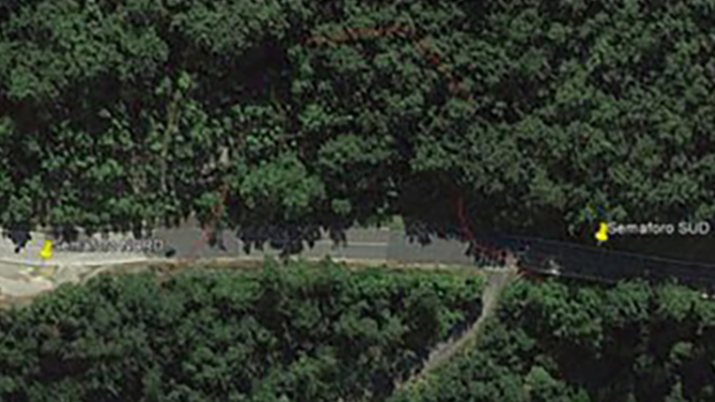
Two three-light traffic lights are installed on each side of the landslide area. They are controlled by the control unit positioned laterally in the parking area located approximately 30 m before the landslide on the side facing north. According to the law, traffic lights must be installed on a pole at a height of between 200 and 300 cm. The standard pole used has a diameter of 10.2 cm and is 360 cm long, it is therefore driven into the ground and then cemented for 60 cm.
The traffic lights must regulate traffic on an alternating one-way stretch of road. Appropriately chosen, but modifiable times are set for switching on the various traffic lights. The times are divided as follows: 30 s green, 15 s yellow (clearance time), 60 s red.
In the event of an alarm signal from the sensors, both traffic lights turn solid red simultaneously and the technician in charge of checking the area is also notified and decides, after the appropriate assessments, whether to deactivate the alarm and reopen traffic on the road.
Alarm control unit for landslide monitoring
The alarm management unit for landslide monitoring is based on a microcontroller which checks the status of the installed sensors at regular intervals of 25 milliseconds. The contact they provide is normally closed, thus ensuring the intrinsic safety of the system.
In the event of activation of one or both sensors or breakage of the cable, the system immediately activates the red lantern of the two traffic lights in order to block road traffic. Similar behavior will occur if the management card microcontroller breaks or the program crashes.
After the traffic lights have been activated, the control unit turns on the telephone dialer (normally off) and when the GSM network is detected, it activates the voice calls provided to the numbers entered in the dialer's directory.
The system will therefore remain in this situation until the arrival of the personnel responsible for controlling the landslide situation.
For more information and to find other useful tools for landslide monitoring, visit the " Slope Stability " section of this site.