
Prototype of peltier cell thermostatic chamber
Prototype of peltier cell thermostatic chamber
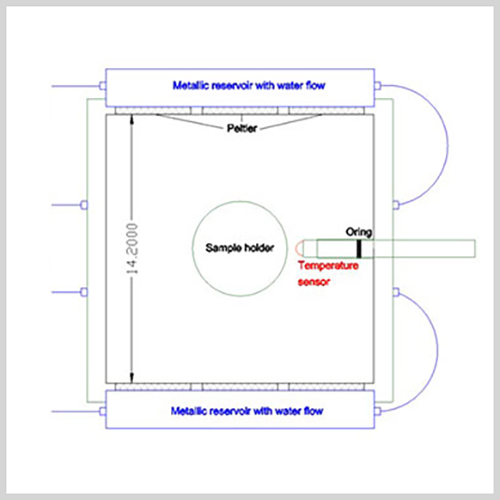
The thermostatic chamber is a device being used to lower the temperature to at least -10 °C inside a 2254 cm3 (14cm x 14cm x 11.5cm) stainless steel container filled with freeze-resistant liquid (e.g. silicone oil or glycol solutions).
Design and technical specifications
It is a square shaped stainless steel box with dimensions 14cm x 14cm x 11.5cm. The steel bottom is fixed to the 10 mm thick PVC base, through 4 screws which have the dual purpose of avoiding movement of the box and ensuring contact with the cooling system placed in contact with the bottom. Laterally the container is supported by the aluminum and PVC heat dissipation system, that will be described later.
The cover is pressed onto the upper edges of the metal box by 4 butterfly screws which ensure the closure of the system. It is made of 10 mm thick PVC and has a transparent window placed centrally, to allow you to see inside of the chamber during the decreasing of temperatures.
Furthermore, the lid is designed to allow oil to be inserted into the chamber through a hole.
The thermal seal of the thermostated chamber is improved by some layers of closed cell insulation glued on the sides not occupied by the heat dissipation system.
Support for displacement sensors
On the side of the container on two opposite sides, there are two threaded supports for anchoring sensors (for example LVDT). The side supports are designed to fit a stainless steel beam with an adjustable hook. The sensor is fixed by screwing the lateral screw, present on the sensor holder, which causes the reduction of the diameter of a steel ring which further crushes the sensor.
The power supply to the cooling system is transmitted by cables with copper conductors with a 0.75 mm2 section and the branches are putted in a safety box made of plastic material which protects against possible short circuits (in any case the power supply is protected from events of this type by interrupting the power supply). The cables run outside the stainless steel container and between the aluminum cooling reservoirs, up to the Peltier cells. The system is powered by two 8-15 Vdc variable voltage power supplies up to a maximum intensity of 20 A (for the operation of the latter, please refer to the manufacturer's manual).
The power supplies have electrical outputs, for banana connector, colored red (positive pole connection) and black (negative connection). The same connections are found on the plastic box that houses the internal electrical connections. The electrical connections are set up on the Tecnopenta instrument exactly like the outputs of the power supplies, therefore: connect, with the supplied safety cable, the red connection at the top right of the chamber with the one at the top right on the first power supply, the one at the bottom on the right with the bottom right of the power supply and so on. The power output can be managed by the operator.
Temperature reduction system

Electrical connections thermostat chamber
The temperature reduction principle exploits the thermal properties of Peltier cells.
Broadly speaking, Peltier cells are plates with a particular structure which, if properly powered, transfer heat from one face to the other through a sort of electronic heat pump.
The thermostatic chamber is equipped with 12 Peltier cells divided into 3 groups of four and therefore positioned on the bottom and on two side walls. Their "cold face" is in contact with the walls of the metal chamber while the "hot face" is in contact with a heat dissipation system made up of aluminum reservoirs where water is circulated (as described later).
The contact of the faces is improved by the use of thermally conductive paste.
Heat dissipation system
The hot face of the Peltier cells should not be overheated for two reasons, the first is that this would prevent the system from cooling the inside of the steel box and the second is that the plastics and cables could be damaged.
The outermost faces of the Peltiers therefore rest on aluminum heat sinks inside which water is circulated which ensures rapid and efficient heat dissipation. In normal operation, the temperature of the heat sink should be similar to that of the supplied water.
The connections of the water circulation system are easily removable because the connections are all quick-connect type.
The presence of water is monitored by a phreatimetric sensor which sounds an alarm if the system is powered without circulating the coolant.
The sensitivity of the sensor can be adjusted based on the conductivity of the liquid used. The entry of water into the circulation system must take place from the hydraulic push-in fitting located on the opposite side to the one with the gray junction box, while the water exits from the large red quick-type connector on the same side. All other quick couplings simply serve the purpose of distributing the coolant to the reservoirs.

Peltier cells
Temperature sensor insertion system

Thermostated cell
The thermostatic chamber is designed to allow the measurement of temperature on various levels with 4 temperature probes placed on one of the vertical sides (west side).
The probes are housed and sealed inside a 4 mm diameter brass tube which, once inserted correctly into the chamber, presses on two o-rings and prevents the liquid inside from escaping.
To obtain the correct positioning of the probes inside the chamber, the following operations must be carried out in sequence:
At this point both o-rings are pressed against the flat wall of the sealing screws on both sides of the chamber and ensure a double seal.
The probes are housed and sealed inside a 4 mm diameter brass tube which, once inserted correctly into the chamber, presses on two o-rings and prevents the liquid inside from escaping.
To obtain the correct positioning of the probes inside the chamber, the following operations must be carried out in sequence:
- insertion of first o-ring and external sealing nut on the brass tube
- inserting the tube into the chamber with the O-ring between the wall and the nut
- external nut fixing
- now work on the internal side of the chamber and insert the o-ring and then the sealing nut
- secure the sealing nut
At this point both o-rings are pressed against the flat wall of the sealing screws on both sides of the chamber and ensure a double seal.
Accessories
The accessories present are: a tripod-type sample holder with adjustable height and a system of heat sinks for diffusing temperatures inside the thermostated chamber. The heat sink system must be positioned interlocking inside the thermostatic chamber and the instructions for positioning are contained in a video on the CD delivered with the system.
Part of the information obtained from the scientific research for here employed equipment can be consulted under the following link:
https://www.witpress.com/Secure/elibrary/papers/STR17/STR17018FU1.pdf
Part of the information obtained from the scientific research for here employed equipment can be consulted under the following link:
https://www.witpress.com/Secure/elibrary/papers/STR17/STR17018FU1.pdf